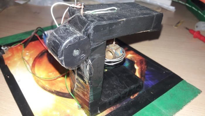
Video 2| Works even on a vibrating table!Fig.1| Take the steel wire and make a coil of 4-5 turns with a diameter slightly greater than the nut taken.Fig.2| Join the three wood pieces and make the shape as shown in fig with the help of nails and make two holes in the middle and upper wood pieces and pass both the ends of the steel coil through the hole of the middle section and wrap the entire structure with black tape except the end of the steel wire.Fig.3| Coil in the middle of the wood piece.Fig. 4| The other end of the coil taken out from the backside of the hole and brought to the base.Fig. 5| Tie the nut with copper wire not very thick and also not very thin but of moderate thickness so that it could easily swing.Fig. 6| Nut tied with the copper wire side view.Pass the end of the copper wire through the top hole such that the nut hangs in between the steel coil shown in fig.7.Fig. 7| Attach the buzzer with the help of tape anywhere or as shown in the fig. and connect the end of the copper wire to one of the terminals of the buzzer.Fig. 8| Connect the other terminal of the buzzer to a wire which will be connected to the LED. Now solder the joints.Fig. 9| Use small nails for fixing connections.Fig. 10| Connections before soldering.Fig. 11| Connections after soldering is done.Fig. 12| The other end of the buzzer is connected to the +ve terminal of the battery and -ve terminal of the battery is connected to the negative terminal of the battery with a wire.Fig. 13| LED connectionsFig. 14| View of the connections made upto this step.Fig. 15| Fix the LED with the help of tape as shown.Fig. 16| Battery and connector joined.Fig. 17| Connect the slider switch in series with the battery and solder the joints.Fig. 18| Switch after soldering done.Fig. 19| Close view of the final connections.Fig. 20| Final complete view of the model.Fig. 21| Top view of the completed model.Fig. 22| Now Switch on the circuit And shake the board as shown in the video the buzzer will ring and the LED will glow.
We use cookies on our website to give you the most relevant experience by remembering your preferences and repeat visits. By clicking “Accept”, you consent to the use of ALL the cookies.
This website uses cookies to improve your experience while you navigate through the website. Out of these, the cookies that are categorized as necessary are stored on your browser as they are essential for the working of basic functionalities of the website. We also use third-party cookies that help us analyze and understand how you use this website. These cookies will be stored in your browser only with your consent. You also have the option to opt-out of these cookies. But opting out of some of these cookies may affect your browsing experience.
Necessary cookies are absolutely essential for the website to function properly. This category only includes cookies that ensures basic functionalities and security features of the website. These cookies do not store any personal information.
Any cookies that may not be particularly necessary for the website to function and is used specifically to collect user personal data via analytics, ads, other embedded contents are termed as non-necessary cookies. It is mandatory to procure user consent prior to running these cookies on your website.